Ultra-wideband antennas fulfill specific spectrum requirements.
Ultra-wideband radio frequency (RF) applications require specialized antennas that can support their unique spectrum and bandwidth characteristics.
Ultra-wideband is a wireless technology that operates over short distances but offers high bandwidth and precise positioning and tracking. It allows for accurate real-time distance measurements without interfering with narrowband or carrier wave transmissions in the same frequency bands. Furthermore, the technology is highly resistant to noise and reflection, making it secure and suitable for various applications.
The Federal Communications Commission (FCC) in the USA has allocated a band which ranges from 3.1 GHz to 10.6 GHz and is centered at 7.5 GHz for the unlicensed use of UWB applications. Meanwhile, in Europe, the Electronic Communications Committee (ECC) has allocated frequency ranges across most countries in the region. These include 3.1 GHz to 4.8 GHz, 6 GHz to 8.5 GHz, and 8.5 GHz to 9 GHz.
Also read; Electric Scooter Price In Chennai: Factors That Affect The Cost
UWB (Ultra-Wideband) is a link format that relies on timing and is particularly suitable for applications that require precise and accurate position measurement within a range of 10 to 30 meters. Compared to other wireless technologies such as Bluetooth or Wi-Fi, UWB offers better reliability and security, making it an ideal choice for applications that require infrequent, but highly precise measurements. Some examples of applications where UWB is a perfect fit include:
Automotive: The precise distance measurement that UWB offers can be integrated into physical or digital car keys that interact with a vehicle based on the user’s proximity to the vehicle.
Industrial: for indoor asset tracking, track and trace, and material flow automation in factories and production lines, using sensors and transponders located along the product-flow path.
Medical: wearable sensors using UWB can also be used to provide precise, real-time vital parameter measurements of patients.
Antenna: first and last part of the wireless signal path
Antennas and their configurations have always faced the complex challenge of meeting many often conflicting objectives. Among the parameters of concern are center frequency, 3-dB bandwidth, radiation patterns, directivity and front/back ratio, side lobes, physical size, impedance, and power handling, to cite a few.
Also read: Mobile Antivirus Unmasked: What You Need To Know For Total Protection
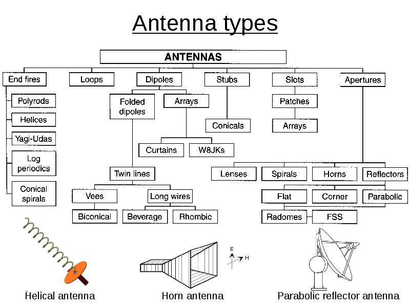
Given that the function of an antenna is simple to describe — to act as a bidirectional transducer between the RF world governed by Maxwell’s equations and the electrical circuit world of volts and amps — it’s astonishing how many different confusions and sizes are in use (Figure 1). But this primarily characterizes their physical construction rather than their electrical and RF parameters.

Figure 1. The family tree of antenna types shows the many configurations in use, each offering different combinations of frequency, bandwidth, directivity, complexity, adjustability, and other parameters as a function of both configuration and specific dimensions (Image: Analog IC Tips).
UWB: that was then, but needs have changed
Traditionally, one key objective in many systems was to keep the antenna bandwidth (as measured between its -3 dB points) to a minimum to avoid picking up extraneous signals or creating unwanted interference. After all, why support out-of-band performance and added received noise, especially if doing so meant compromising on other factors?
One common metric of the bandwidth parameter is not the absolute bandwidth value but instead the fractional bandwidth (FBW). The FBW is the ratio of the frequency span (highest frequency minus lowest frequency) divided by the center frequency. The fractional bandwidth can range from zero to two and is often quoted as a percentage between 0% and 200%). The higher the percentage, the wider the bandwidth.
A note about UWB terminology: the phrase “ultra-wideband,” sometimes spelled ultrawideband, has two somewhat different meanings. In the context of antennas, it relates to the FBW as discussed previously. When it comes to the electromagnetic spectrum, however, the term “ultra-wideband” is also used to describe higher frequencies where more bandwidth is available.
It would be nice to have a simple guideline indicating the approximate FBW of different antenna types such as dipole, Yagi-Uda, patch, horn, dish, and so on — but that’s not possible. The reason is that antennas, perhaps more so than most components, have many tradeoffs in their design and physical dimensions. They have an extraordinary number of degrees of freedom, and thus, their parameters, including FBW, can be balanced against each other to find an “optimum” design for a given application.
Also read: Fairview Microwave Launches Groundbreaking Series Of 5G Amplifiers For Low And Mid Frequency Bands
The FBW of almost any antenna can be made larger or smaller by trading off against its other parameters such as directivity (gain), side lobes, radiation pattern, physical size, and number of elements for multi-element designs. For example, the FBW of a classic Yagi-Uda antenna can be adjusted from a few percent to tens of percent by changing the number and spacing of its elements, their thickness, and other physical attributes.
Some specialists consider an antenna with an FBW of 20% or higher to be an ultra-wideband antenna (UWB) while others say that only those with an FBW above 50% are UWB antennas. The FCC and the International Telecommunication Union Radiocommunication Sector (ITU-R) currently define UWB as an antenna transmission for which emitted signal bandwidth exceeds the lesser of 500 MHz or 20% of the arithmetic center frequency. Due to the potential for confusion, it’s often a good idea to ask for clarification when discussing the topic.
For many years, the directive to antenna designers or specifiers was simple: keep FBW as narrow as possible to minimize noise, interference, and other unwanted consequences, while meeting other objectives. Now, the advent of wideband and multiband applications has turned that rule around to where a UWB antenna with a large FBW is desirable or mandated. In fact, there are many recent academic papers describing novel or innovative antenna configurations with UWB characteristics.
Off-the-shelf UWB antennas
UWB antennas are sometimes fabricated as part of the product’s circuit board, which offers cost savings in the bill of materials (BOM) but requires a larger amount of board “real estate” and constrains the adjacent board layout. Fortunately, the wide use of UWB applications means that standard, off-the-shelf discrete antennas are available for segments of the UWB operating bands. As UWB is a higher-frequency arrangement, antennas tend to be smaller, with dimensions on the order of a few centimeters or less; although there are exceptions
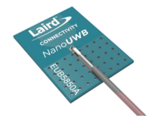
Figure 2. This monopole UWB antenna is a small, simple-to-apply patch design with an integral 100-mm cable and connector (Image: Laird Connectivity).
Just as with narrowband antennas, UWB antennas are offered in a wide range of physical designs and appearances. Internal antennas include chip, board, flexible, and patch antennas, while external antennas include whip, blade, puck, and dome configurations. Three different examples illustrate the variety and performance of UWB antennas:
The NanoUWB Planar Monopole Antenna from Laird Connectivity covers 5850-8250 MHz and is a stick-on patch design that measures 20 × 15 × 1.67 mm (Figure 2). It comes with a 100-mm cable fitted with a standard MHF1 /U.FL connector.
The 50-Ω unit features a peak gain of +3.9 dBi and VSWR below 2 across the band when measured on a 1.6 mm thick polycarbonate surface (Figure 3) — note that antenna performance is affected by the type of material to which it is attached.
Also read; U-Blox Unveils NEO-F10N: The Latest Advancement In Positioning Technology
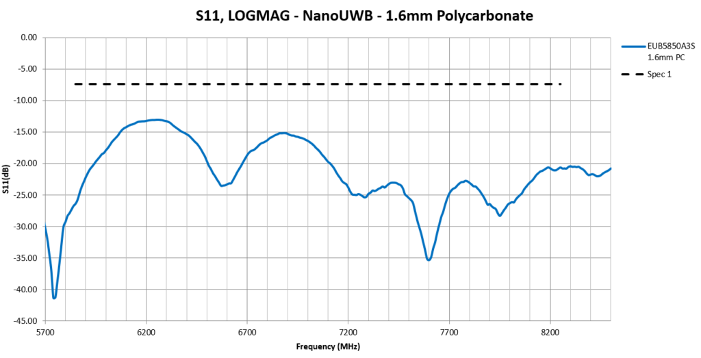
Figure 3. The S11 VSWR graph for the antenna is just one of many graphs on the extensive data sheet, including radiation patterns and effects of nearby materials (Image: Laird Connectivity).
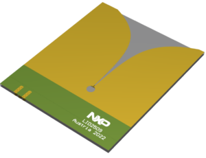
Figure 4. This co-planar tapered-slot antenna is designed with connector pads at its edge for convenient integration with the overall product design and packaging (Image: NXP Semiconductors).
The NXP LID2509 is a linearly polarized “Vivaldi” antenna (a type of co-planar tapered-slot antenna) for 3.5 GHz to 9 GHz with a gain of around 6 dBi (Figure 4). This directional antenna is designed for UWB radar measurements but can also be used for UWB ranging or any other wireless technology operating in its bandwidth. The antenna features “landing pads” for a user-provided edge-mounted SMA connector for the transition to a microstrip line.
VSWR is below 1.5, and return loss is greater than 13 dB for this 77.25 mm × 63 mm × 1.8 mm antenna (Figure 5).

Figure 5. The two top-tier parameters of VSWR and return loss for this “Vivaldi” antenna are shown on the same graph for convenience (Image: NXP Semiconductors).
Finally, for visible ceiling installations in offices, residential, and industrial settings, the disk-like Comprod UWB-1301000-NF covers 130 to 1000 MHz (Figure 6). The antenna is terminated with a standard N Female connector with a 15.25-inch diameter, and its low-profile 0.1-inch thickness is barely noticeable on the ceiling.
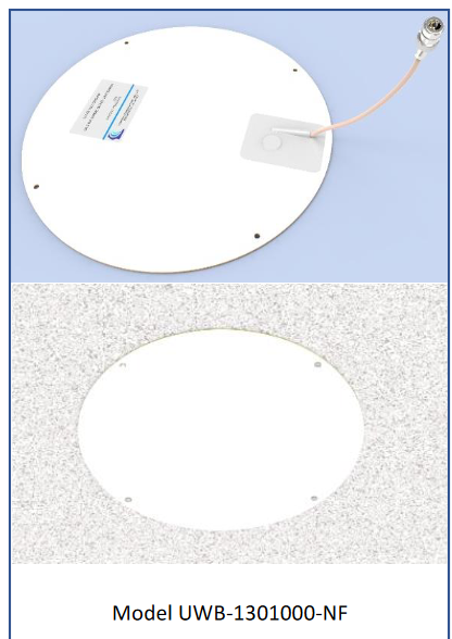
Figure 6. Not all antennas go into or alongside a product; this disk antenna is designed for convenient ceiling mounting and includes a cable terminated with a standard Type N connector; the upper image is the antenna itself, while the lower image is the antenna as installed (Image: Comprod).
Typical VSWR is under 1.8 (2.0 maximum) for this specialized unit (Figure 7).
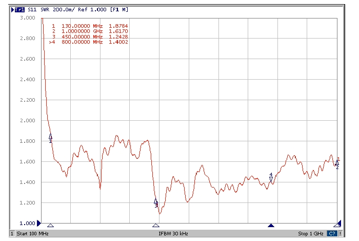
Figure 7. The ceiling-disk antenna covers a lower part of the spectrum — 130 to 1000 MHz — than many other available UWB antennas (Image: Comprod).
Conclusion
Ultra-wideband (UWB) antennas are needed to support the diverse multiband and wideband applications, which are now getting greater attention. Many standard antennas are available in various form factors which are designed specifically for the UWB situations. Using these antennas, designers can quickly select and site a UWB antenna on their circuit board or enclosure and move on to the next stages of their project.
Related EE World Content
Internal antenna transmits and receives UWB signals
UWB applications bring design decisions
UWB transceiver IC provides positioning at low power
UWB radar sensor for people positioning
UWB sensors compete with RFID, BLE apps
Add UWB hardware and software to IC designs
UWB antennas enable precise real-time location services
UWB: A reborn standard for high-accuracy location services
FAQ on fractal antennas, Part 1
FAQ on fractal antennas, Part 1The microstrip antenna, Part 1: Basics
The microstrip antenna, Part 2: Implementation
Demonstrating antenna diversity, Part 3: The Yagi antenna
External References
International Journal of Antennas and Propagation, “Wideband and UWB Antennas for Wireless Applications: A Comprehensive Review”
IntechOpen, “Ultra-Wideband Antenna and Design”
National Institute of Health, National Library of Medicine, “Ultrawideband Antennas: Growth and Evolution”
Latest Posts
Nigeria’s 5G Reality: Beyond the Hype, Into the Practical
The buzz around 5G has reached Nigeria, with major network providers like...
2 months AgoETSI Launches Industry Group to Tackle 6G Multiple Access Techniques
ETSI has established a new Industry Specification Group (ISG) focused on Multiple...
3 months AgoUnderstanding the Role of a Scheduler in 5G Networks
A scheduler dynamically allocates resources, including time, frequency, and power, to serve...
3 months AgoMorse Micro Unveils Next-Generation Wi-Fi HaLow SoC with Enhanced Performance
Morse Micro has announced the launch of its second-generation MM8108 System-on-Chip (SoC)....
3 months Ago





Leave a comment